
Polycarbonate material parts can use either a break-away support or the soluble support. Either a break-away support material or a soluble support material is used. Any cantilevered feature would need this, for example. Since the part is built in the vertical direction, one slice at a time, it may be necessary to have a sacrificial support structure on which to build. Some post-printing work may be necessary to remove support material and/or finish the surface properties depending on how the parts are to be used. Parts which would be difficult (or impossible) to machine can be readily printed as a single part. The maximum build volume is 16 in W x 14 in D x 16 in H (406.4 mm x 355.6 mm x 406.4 mm). A video posted from Stratasys demonstrates this (Oops! looks like he forgot to wear safety glasses). The BASS support material can be pulled or broken away using carving tools, dental picks, and pliers. Appropriate personal protective equipment (PPE) should be worn, i.e., safety glasses and working gloves.

The material is a polyphenylene ether / high impact polystyrene blend. The Break-Away Support System, as the name implies, is a support material that is broken away from the part. Depending on the part and the state of the solution, parts may require a few hours to a day or so to fully remove the support material. However, if there are fine features, the soluble support system may be the best solution. We generally use the BASS system, as the removal of the soluble support requires immersing the part into an alkaline bath. There are two kinds of support material: The break-away support system (BASS) and the soluble support system. This figure shows the build parameters of a simple block part. By default, each alternating layer is raster-filled in alternating directions for higher strength. Parts can be made as completely solid, or to save on material and time as a sparse build, where the internal volume is similar to a honeycomb structure. The tool path is defined by contour lines that outline the part, and raster, or fill lines. In this way, time can be saved by printing a number of parts, as long as they can fit within the envelope of the machine: 16 in W x 14 in D x 16 in H (406.4 mm x 355.6 mm x 406.4 mm).
Stratasys product timeline 3d printers fortus software#
Once print jobs are generated, another software application is used to arrange them on the build area and send them to the machine. After orienting the part for the build, the software then slices horizontal build planes and creates toolpaths for each slice of the part based on the configuration of the machine and user-selectable parameters. SSAG Fortus 450mc 3D Printer.ĬAD models are imported in the stereo lithography (.STL) file format to the printer software. size (provide units) Length x Width x Height:

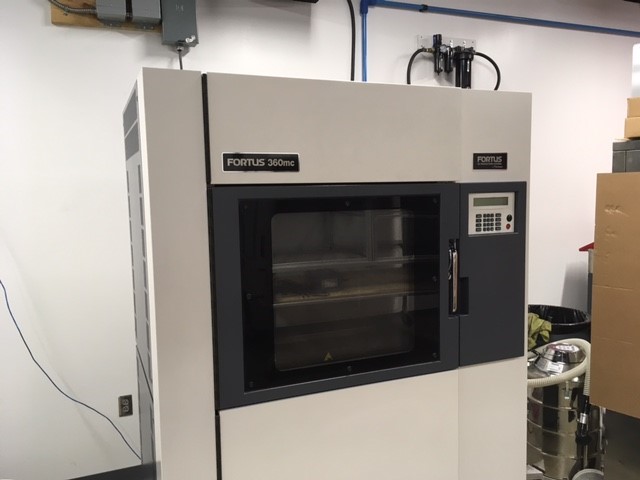
NPS Department or Group: Project Name: Principal Investigator: Research or Instruction: Material Provided by: Approx. Information needed with (.stl) job request: Interested in producing parts? Contact a technician and provide the following information (login to Wiki required to access link). instructional parts, research, and thesis projects. The 3D printer is open to the NPS community on a cost-reimbursable basis for appropriate activities, e.g. This Wiki is intended to provide information for potential users of the machine. In June 2020, the machine was replaced with its updated version, the Fortus 450mc. The machine employed fused deposition modeling (FDM) for additive manufacturing of three-dimensional parts from computer-aided design (CAD) geometry. The NPS Space Systems Academic Group originally started 3D printing, or additive manufacturing, back in July 2008 with its Fortus 400mc 3D Printer. Notice: The 3D Printer is now in Halligan Hall and is up and running. Space Systems Academic Group Rapid Prototyping / Additive Manufacturing (3D Printer).


 0 kommentar(er)
